QSFP+
QSFP+ — Quad Small Form-Factor Pluggable Plus
Детальное описание разъема QSFP+
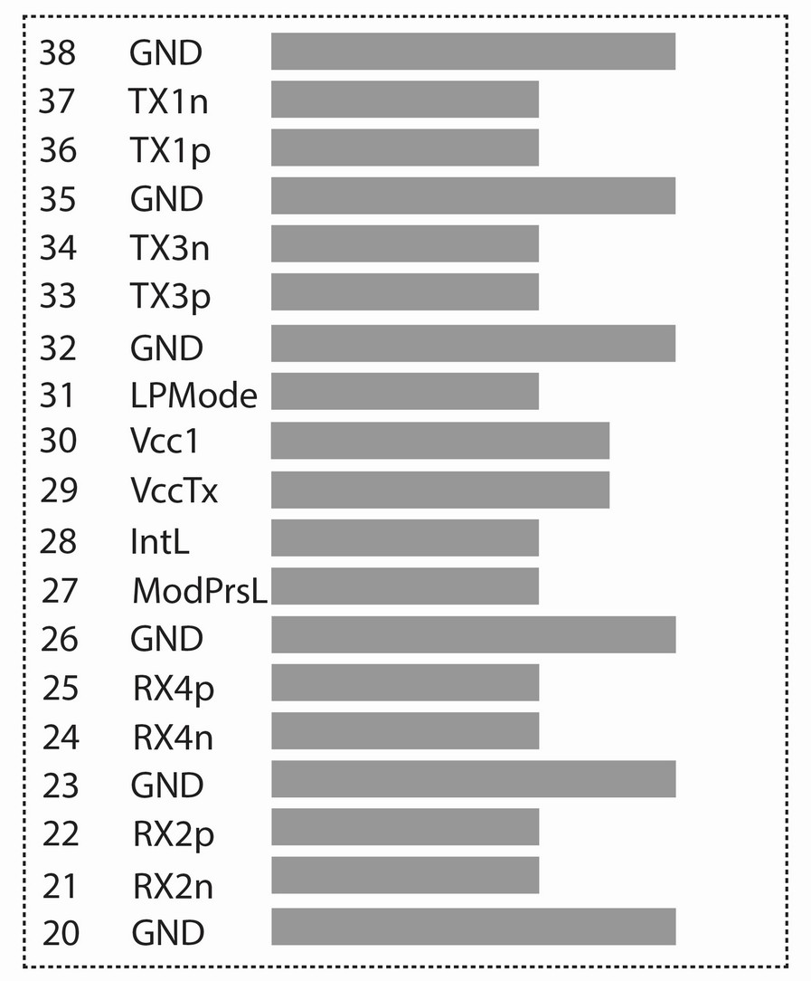
Рисунок 1. Верхняя сторона разъема QSFP+ с контактными площадками (взгляд сверху)

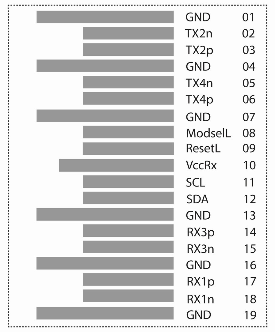
Рисунок 2. Нижняя сторона разъема QSFP+ с контактными площадками (взгляд снизу)

Таблица №1. Назначение контактных площадок QSFP+ разъема
| Номер контактной площадки (PIN) | Логика | Обозначение | Наименование/Описание | Примечание № |
| 1 | GND | Module Ground | 1 | |
| 2 | CML-I | Tx2n | Transmitter Inverted Data Input | |
| 3 | CML-I | Tx2p | Transmitter Non-Inverted Data Input | |
| 4 | GND | Module Ground | 1 | |
| 5 | CML-I | Tx4n | Transmitter Inverted Data Input | |
| 6 | CML-I | Tx4p | Transmitter Non-Inverted Data Input | |
| 7 | GND | Module Ground | 1 | |
| 8 | CML-I | ModSelL | Module Select | 2 |
| 9 | CML-I | ResetL | Module Reset | 2 |
| 10 | Vcc Rx | +3.3 V Receiver Power Supply | ||
| 11 | LVCMOS-I | SCL | 2-wire Serial Interface Clock | 2 |
| 12 | LVCMOS-I/O | SDA | 2-wire Serial Interface Data | 2 |
| 13 | GND | Module Ground | 1 | |
| 14 | CML-O | Rx3p | Receiver Non-Inverted Data Output | |
| 15 | CML-O | Rx3n | Receiver Inverted Data Output | |
| 16 | GND | Module Ground | 1 | |
| 17 | CML-O | Rx1p | Receiver Non-Inverted Data Output | |
| 18 | CML-O | Rx1n | Receiver Inverted Data Output | |
| 19 | GND | Module Ground | 1 | |
| 20 | GND | Module Ground | 1 | |
| 21 | CML-O | Rx2n | Receiver Inverted Data Output | |
| 22 | CML-O | Rx2p | Receiver Non-Inverted Data Output | |
| 23 | GND | Module Ground | 1 | |
| 24 | CML-O | Rx4n | Receiver Inverted Data Output | |
| 25 | CML-O | Rx4p | Receiver Non-Inverted Data Output | |
| 26 | GND | Module Ground | 1 | |
| 27 | LVTTL-O | ModPrsL | Module Present, internal pulled down to GND | |
| 28 | LVTTL-O | IntL | Interrupt output, should be pulled up on host board | 2 |
| 29 | Vcc Tx | +3.3 V Transmitter Power supply | ||
| 30 | Vcc 1 | +3.3 V Power Supply | ||
| 31 | LVTTL-I | LPMode | Low Power Mode | 2 |
| 32 | GND | Module Ground | 1 | |
| 33 | CML-I | Tx3p | Transmitter Non-Inverted Data Input | |
| 34 | CML-I | Tx3n | Transmitter Inverted Data Input | |
| 35 | GND | Module Ground | 1 | |
| 36 | CML-I | Tx1p | Transmitter Non-Inverted Data Input | |
| 37 | CML-I | Tx1n | Transmitter Inverted Data Input | |
| 38 | GND | Module Ground | 1 |
Примечание к Таблице №1:
1. GND is the symbol for signal and supply (power) common for the QSFP+ module. All are common within the QSFP+ module and all module voltages are referenced to this potential unless otherwise noted. Connect these directly to the host board signal-common ground plane.
2. Vcc Rx, Vcc1 and Vcc Tx are the receiver and transmitter power supplies and shall be applied concurrently. Recommended host board power supply filtering is shown below. Vcc Rx, Vcc1 and Vcc Tx may be internally connected within the QSFP+ Module module in any combination. The connector pins are each rated for a maximum current of 500 mA.